
Learn the Interfacing LCD in Arduino. We will learn about the basics and working of LCD. In this 16×2 character LCD and Arduino UNO Board are used.
First, let’s start with the basics of all the 16 pins of the 16×2 Character LCD.
Ground Pin
+5V Pin
Contrast Adjustment Pin
Register Select Pin
Read/Write Signal
Enable Pin
Data Bus line 0-7
+4.2V for LED
Power Supply for Black – 0V
Step 1: Required Components
16×2 Character LCD x 1
Breadboard x 1
Arduino Uno Board x 1
10K Potentiometer x 1
Jumper Wires
Step 2: Circuit Time
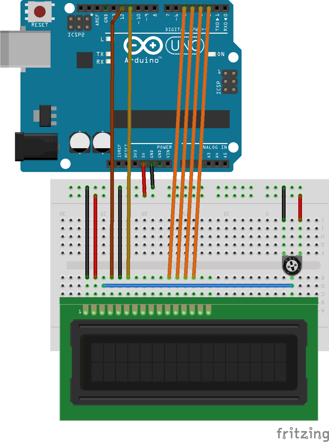
Make a circuit as per the given diagram. Here Arduino pin 12 is connected to Resister Select, pin 11 is connected to enable, pin 5 to 2 are connected to Data Bus Line 4 to 7 and Potentiometer output is connected to Contrast adjustment pin.
Step 3: Code Time
This is the code for LCD. Here, we have imported the library of “LiquidCrystal” to use the functions of the LCD. After this LCD is initialized with the LCD pins. In Setup, LCD is begun with the 16 columns and 2 rows. In the loop, the cursor of the LCD is set to the fourth column and second row. Setting up cursor is not compulsory, it will automatically set it as the first column and first row. At last, the “IOTGUIDER” is printed to the LCD.
Step 4: Upload the code to Arduino
Upload the above-given code to the Arduino UNO Board after the components are set as per the Circuit Diagram. The 16×2 LCD will show “IOTGUIDER” written on the display.
Learn more information about uploading code to Arduino Uno.
Well explained for beingers like myself thank you mark
Thank you. Please share it among your friends and network.