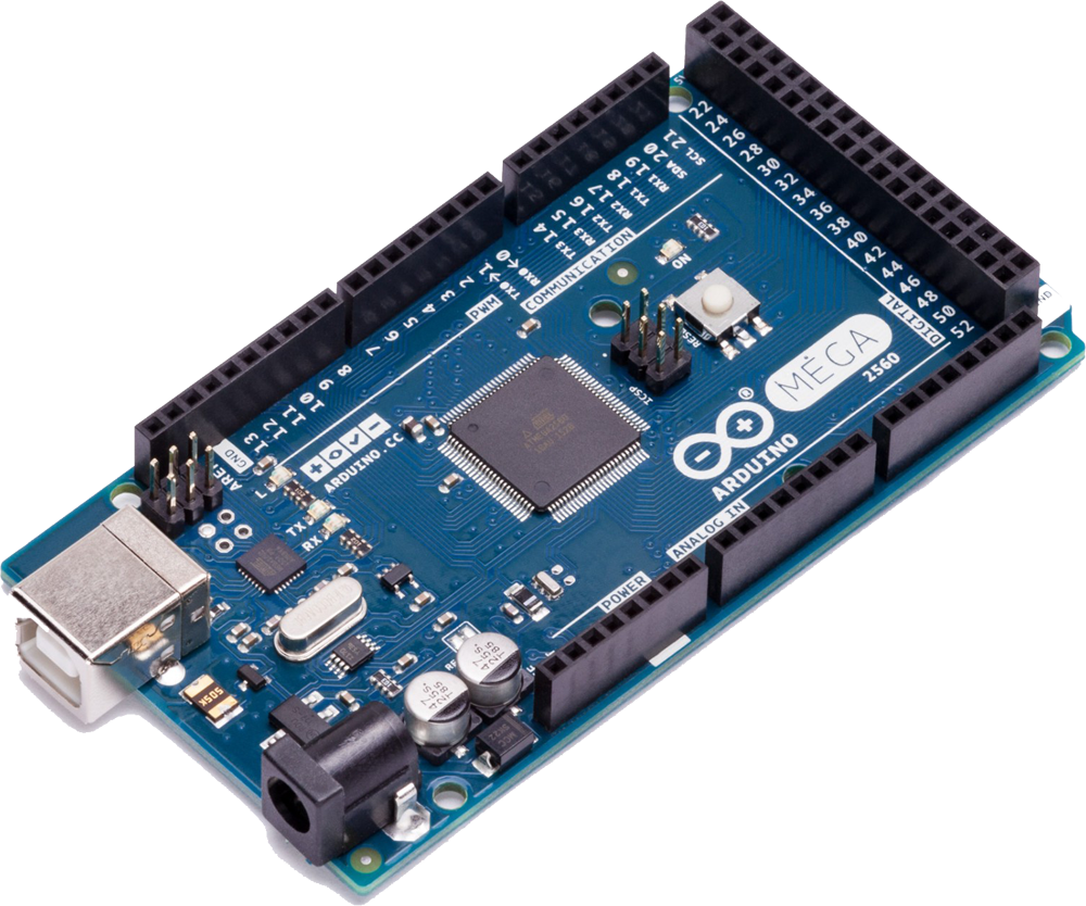
What is Arduino Mega 2560 Board
Arduino Mega 2560 Board is an open-source microcontroller board based on the ATmega2560 chip. Arduino Mega 2560 features 54 digital I/O pins (15 pins can be used as PWM), 16 analog inputs, a 16 MHz quartz crystal, a USB connection, Power Jack, and a Reset Button. Learn about Arduino Boards Family.
Basic Hardware of Arduino/Genuino Mega 2560
Arduino/Genuino Mega 2560 Board contains
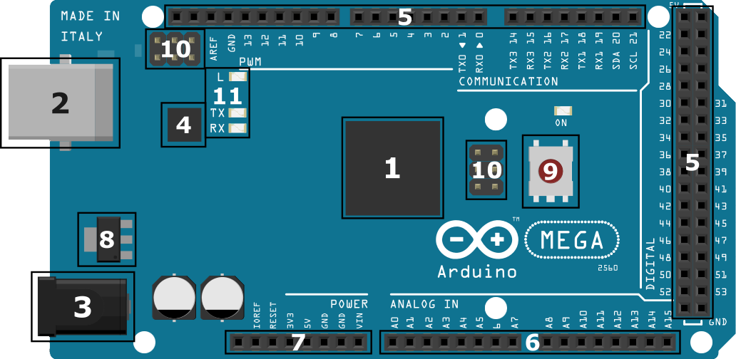
- Micro-controller (ATmega2560) – Micro-controller ATmega2560(a single chip micro-controller) created by Amtel is used in Arduino Mega. It has 256KB programmable flash memory(in which 8KB used by bootloader), 8KB SRAM, 4KB EEPROM (Electrically Erasable Programmable Read-Only Memory).
- USB Connector – USB connector is used for two purposes in Arduino. The first one is to load the Mega 2560 user program to Arduino using Arduino IDE and another one is to power Arduino Board. Learn uploading program to Arduino board.
- Power Port – The Arduino can be powered using AC to DC adapter or battery. 2.1mm center-positive plug is used to power the Arduino Board. Recommended input power Voltage is 7-12V.
- USB Interface Chip – Arduino has Atmel ATmega16U2 as a USB interface chip. It is a bridge between Computer’s USB Port and the main processor’s serial port.
- Digital I/O Pins – Arduino MEGA board has 54 Digital I/O Pins. The 54 Digital I/O Pins are numbered from Pin 0 to Pin 53. In which 15 of them are PWM (Pulse-Width Modulation) Digital I/O Pins. PWM pins are used to simulate analog output. Digital I/O Pins are used to take Digital Input or provide Digital Output in Arduino MEGA Board.
- Analog Input Pins – Arduino MEGA board has 16 Analog Input Pins. The 16 Analog Input Pins are numbered from Pin A0 to Pin A15. Analog Input Pins are used to take the signal from analog sensors and convert it into a digital value. The pins measure the voltage not current because it has a very high value of internal resistance. So the value of current is much smaller as compared to the voltage.
- Power Pins
- Vin – The input voltage to the Arduino/Genuino board when it’s using an external power source.
- 5V – This pin outputs a regulated 5V from the regulator on the board. Supplying voltage via the 5V or 3.3V pins bypasses the regulator, and can damage your board. We don’t advise it.
- 3V3 – This pin outputs a regulated 3.3 volt supply generated by the onboard regulator. The maximum current draw from this pin is 50 mA.
- GND – Ground pins.
- IOREF – This pin on the Arduino/Genuino board provides the voltage reference with which the microcontroller operates. A properly configured shield can read the IOREF pin voltage and select the appropriate power source or enable voltage translators on the outputs to work with the 5V or 3.3V.
- Voltage Regulator – The main work of the Voltage Regulator is to regulate the input and output voltage of the Arduino MEGA board. It also regulates the voltage for 5V and 3V3 pins. If the power voltage of the power port is more than 12V, the voltage regulator may overheat and damage the board.
- Master Reset Button – Master Reset Button is used to reset the Arduino MEGA board and restart the running program from starting. It is useful when the programmer wants to run the program from the starting point. When Master Reset Button is pressed, it sends the logical pulse to the reset pin of the micro-controller.
- ICSP Header Pins – a Full form of ICSP is In-Circuit Serial Programming also called In-System Programming (ISP). It is used to program AVR microcontrollers. You can use the Arduino ISP to upload sketches directly on the AVR-based Arduino boards without the need of the bootloader ICSP Header Pins contains six pins MISO(Master In Slave Out), +Vcc, SCK(Serial Clock), MOSI(Master Out Slave In), Reset, GND.
- RX/TX LED – The RX and TX LEDs on the board will start flashing when data is being transmitted via USB-to-serial chip and USB connection to the computer.
Content and image source: arduino.cc
what is function of SDA and SCL
These pins are used for components like RTC.