
What is Arduino UNO WiFi board?
Arduino UNO WiFi Rev2 is powered by brand new 8-bit ATMEGA4809. The board contains 14 digital I/O pins, 6 analog inputs, USB connection, Power Jack and a Reset Button. It adds WiFi to your existing device. It has built-in onboard LSM6DSMTR IMU (Inertial Measurement Unit). The board has an ATECC608A Cryptographic co-processor chip. This chip is helpful for secure hardware-based key storage and security.
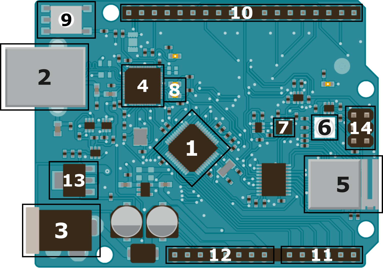
Basic Hardware of Arduino UNO WiFi Rev2
Arduino UNO WiFi contains
-
Micro-controller (ATMEGA4809)
- It has Atmel ATmega4809 Micro-controller. It offers 48KB programmable flash memory, 6144 Bytes SRAM, 256 Bytes EEPROM. ATmega4809 microcontroller operates between 1.8 to 5.5 volt. It contains a total of 48 input/output pins.
-
USB Connector
- It has a USB-B port for connection. The USB connector has mainly two purposes. To load user program to Arduino using Arduino IDE and to power the Arduino Board. Learn Arduino programming basics.
-
Power Port
- The power port is useful for supplying power Arduino from an external source. You can use an AC to DC adapter or battery to power it. 2.1mm center-positive plug is used to power the Arduino Board. Recommended input power Voltage is 7-12V.
-
ISP Flash and USB Controller
- Arduino UNO WiFi has Atmel ATmega32U4 as ISP Flash and USB Controller chip. ISP Flash stands for In-system programming Flash. It the main bridge between Arduino USB and Micro-controller.
-
WiFi Module (NINA-W102)
- WiFi support is enabled with the u-blox NINA-W102 Module. ESP-32 also contains the same chip for WiFi support.
- WiFi support is enabled with the u-blox NINA-W102 Module. ESP-32 also contains the same chip for WiFi support.
-
RGB LED
- Arduino UNO WiFi has built-in RGB LED which can be programmable.
-
IMU (Inertial Measurement Unit)
- It contains onboard LSM6DSMTR IMU which is helpful for Accelerometer, Gyroscope, Temperature, and 3 Axis Sensor.
-
RX/TX LED
- The RX and TX LEDs on the board will flash when data is being transmitted via the USB-to-serial chip and USB connection to the computer.
-
Master Reset Button
- This Button is useful for resetting the Arduino UNO board and restarting the program from the origin. It is useful when the programmer wants to run the program from the starting point. Pressing the Master Reset Button, it sends the logical pulse to the reset pin of micro-controller.
-
Digital I/O Pins
- Arduino UNO WiFi board contains 14 Digital I/O Pins numbered from D0 to D13. In which 6 of them are PWM (Pulse-Width Modulation) Digital I/O Pins. Pin no 3, 5, 6, 9, 10, and 11 are having a (~) symbol on it are PWM Pins. PWM pins simulate analog output. Digital I/O Pins are useful to take Digital Input or provide Digital Output.
- Arduino UNO WiFi board contains 14 Digital I/O Pins numbered from D0 to D13. In which 6 of them are PWM (Pulse-Width Modulation) Digital I/O Pins. Pin no 3, 5, 6, 9, 10, and 11 are having a (~) symbol on it are PWM Pins. PWM pins simulate analog output. Digital I/O Pins are useful to take Digital Input or provide Digital Output.
-
Analog Input Pins
- The board contains 6 Analog Input Pins numbered from Pin A0 to Pin A5. Analog Input Pins are useful to take the signal from analog sensors and convert it into a digital value. The pins measure the voltage not current because it has a very high value of internal resistance. So, the value of the current is much smaller as compared to the voltage.
-
Power Pins
- Vin – The input voltage to the Arduino board when it’s using an external power source.
- 5V – This pin outputs a regulated 5V from the regulator on the board. Supplying voltage via the 5V or 3.3V pins bypasses the regulator, and can damage your board. We don’t advise it.
- 3V3 – This pin outputs a regulated 3.3 volt supply generated by the onboard regulator. The maximum current draw from this pin is 50 mA.
- GND – Ground pins.
- IOREF – This pin on the Arduino board provides the voltage reference with which the microcontroller operates. A properly configured shield can read the IOREF pin voltage. It selects the appropriate power source or enables voltage translators on the outputs to work with the 5V or 3.3V.
-
Voltage Regulator
- The main work of the Voltage Regulator is to regulate the input and output voltage of the Arduino UNO board. It also regulates the voltage for 5V and 3V3 pins. If you supply power more than 12V, it may overheat and damage the board.
-
ICSP Header Pins
- ICSP is In-Circuit Serial Programming also called In-System Programming (ISP). It is used to program AVR microcontrollers. You can use the Arduino ISP to upload sketches directly on the AVR-based Arduino boards without the need for the bootloader. ICSP Header Pins contains six pins MISO, +Vcc, SCK, MOSI, Reset, GND.
Note: In Arduino UNO WiFi Rev2, Built-in LED Pin is 25 instead of Pin number 13 (Generally for Arduino Boards).
Content and image source: arduino.cc