
Learn the Interfacing LDR in Arduino. We will learn about the basics and working of LDR. In this LDR and Arduino Uno board is used. You can use it as per your requirements. LDR is a resistor that varies its resistance depending on the light of the outside environment. LDR is also known as Photoresistor and available in 5mm, 7mm, 10mm, and many other sizes.
Step 1: Required Components
LDR x 1
Breadboard x 1
Arduino Uno Board x 1
100K Resistor x 1
Jumper Wires
Step 2: Circuit Time
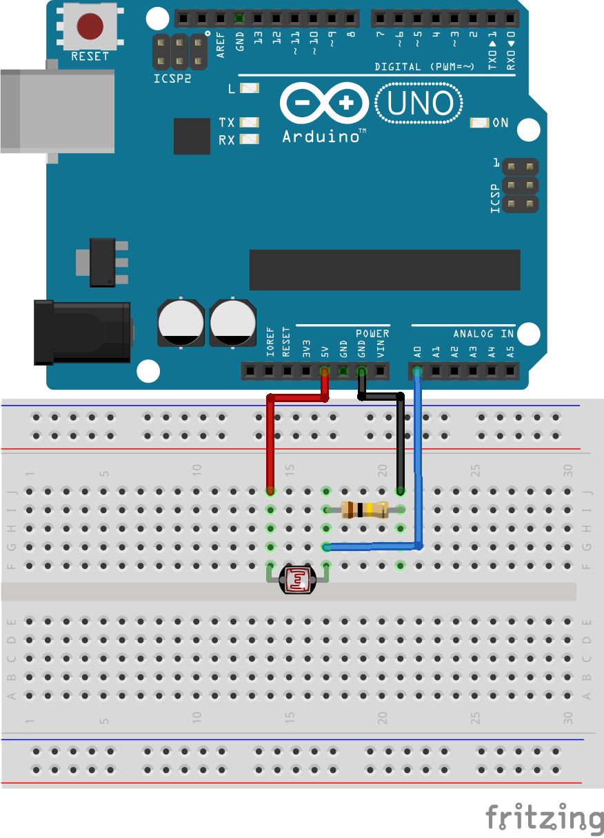
Make a circuit as per the given diagram. Here Arduino pin A0 is connected to one side of LDR, VCC is connected to another side.
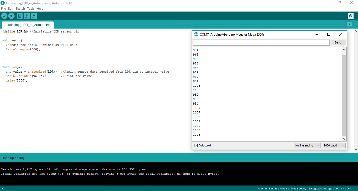
Step 3: Code Time
This is the code for LDR. Here, LDR is defined as A0. In Setup, the Serial Monitor is begun at 9600 Baud. In the loop, read the analog pin value and stored in the variable. After that printed that value to the serial.
Step 4: Upload the code to Arduino
Upload the above-given code to the Arduino UNO Board after the components are set as per the Circuit Diagram. The analog value of LDR will be printed on the Serial Monitor.
Learn about uploading code to Arduino Board.