What is the Arduino Nano Board?
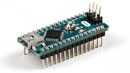
Arduino Nano Board is an open-source microcontroller board based on ATmega328p chip. It offers features similar to Arduino UNO but in a small form factor. Programming of the board is done by Arduino IDE using both the offline as well as online editor.
It consists of (PQFP) Plastic Quad Flat Pack with 32 pins, whereas Arduino UNO consists of (PDIP) Plastic Dual-In-Line with 30 pins. The two extra pins in Arduino Nano are analog, leaving Arduino Nano with 8 analog pins. Arduino Nano only has a Mini-B USB port for both programming purposes and serial monitoring.
Basic Hardware of Arduino Nano
Arduino Nano Board contains
-
Micro-controller (ATmega328P)
The micro-controller used in Arduino Nano is ATmega328P (a single chip micro-controller) created by Atmel. It has 32KB programmable flash memory, 2KB SRAM, 1KB EEPROM (Electrically Erasable Programmable Read-Only Memory). ATmege328P micro-controller operates between 1.8 to 5.5 volt.
-
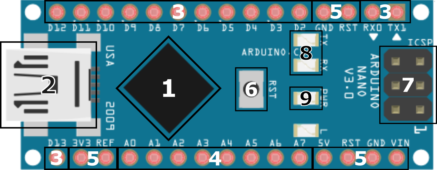
Mini-B USB Port
Mini-B USB port serves several purposes such as programming Arduino Nano, serial monitoring and also supply power to the board.
-
Digital I/O Pins
In Arduino Nano board 14 Digital I/O Pins numbered from Pin D0 to Pin D13. In which 6 of them are PWM (Pulse-Width Modulation) Digital I/O Pins. PWM pins simulate analog hardware output while other pins simulate software analog output. Digital I/O Pins take Digital Input or provide Digital Output in Board.
-
Analog Input Pins
There is a total of 8 analog pins on the Arduino Nano board. The 8 Analog Input Pins numbered from Pin A0 to Pin A7 take the signal from analog sensors and convert it into a digital value. The pins measure the voltage not current because it has a very high value of internal resistance. So, the value of the current is much smaller as compared to the voltage.
-
Power Pins
- Vin – The input voltage to the Arduino/Genuino board when it’s using an external power source.
- 5V – This pin outputs a regulated 5V from the regulator on the board. Supplying voltage via the 5V or 3.3V pins bypasses the regulator, and can damage your board. We don’t advise it.
- 3V3 – This pin outputs a regulated 3.3 volt supply generated by the onboard regulator. The maximum current draw from this pin is 50 mA.
- GND – Ground pins.
- IOREF – This pin on the Arduino/Genuino board provides the voltage reference with which the microcontroller operates. A properly configured shield can read the IOREF pin voltage and select the appropriate power source or enable voltage translators on the outputs to work with the 5V or 3.3V.
-
Master Reset Button
Master Reset Button will reset the Arduino Nano board and restart the running program from starting. It is useful when the programmer wants to run the program from the starting point. On pressing the Master button, a logical pulse will be sent to the reset pin of the microcontroller.
-
ICSP Header Pins
The full form of ICSP is In-Circuit Serial Programming also called In-System Programming (ISP). ICSP programs AVR microcontrollers. You can use the Arduino ISP to upload sketches directly on the AVR-based Arduino boards without the need of the bootloader ICSP Header Pins contains six pins MISO(Master In Slave Out), +Vcc, SCK(Serial Clock), MOSI(Master Out Slave In), Reset, GND.
-
RX/TX LED
The RX and TX LEDs on the board will flash when data is being transmitted via the USB-to-serial chip and USB connection to the computer.
-
Power LED
The Power LED on the board indicates power supplied to the board.
Content and image source: arduino.cc