Learn interfacing 16×2 LCD in Raspberry Pi. We will also learn the basics and work of 16×2 Character LCD. So, let’s start.
First, let’s start with the basics of all the 16 pins of the 16×2 Character LCD in Raspberry Pi.
Ground Pin
+5V Pin
Contrast Adjustment Pin
Register Select Pin
Read/Write Signal
Enable Pin
Data Bus line D0 – D7
+4.2V for LED
Power Supply for Black – 0V
Step 1: Required Components
16×2 Character LCD Display x 1
Breadboard x 1
Raspberry Pi x 1
10K Potentiometer x 1
Jumper Wires
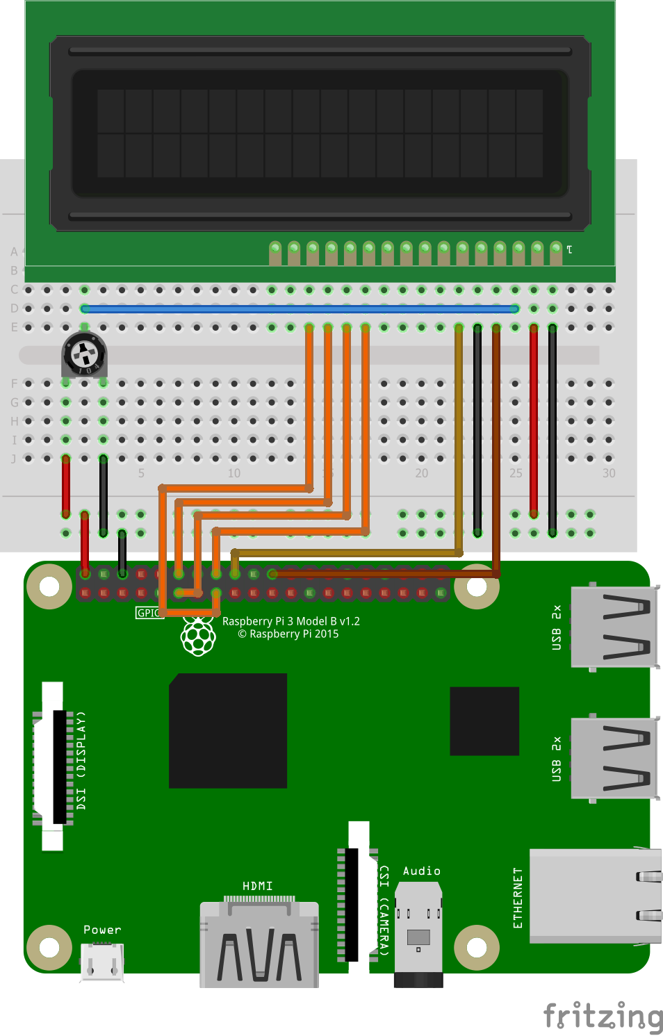
Step 2: Circuit Time
Make the circuit as per the given diagram. There are two ways to connect LCD, 4-bit mode and 8-bit mode. In 4 bit mode, data bytes are split in Higher-order and Lower order address bus and sent through four-wire D4 – D7. In 8 bit mode, data bytes are sent all at once using 8 data pins D0 – D7.
We are going to connect the LCD in 4-bit mode. Connect Resistor Select (RS) pin to GPIO 25 and Enable pin to GPIO 24. Data bus pin are connected as follows, D4 > 23, D5 > 17, D6 > 18, D7 > 22. Connect potentiometer output to contrast adjustment pi V0 of LCD.
Step 3: Code Time
For this, we are going to install Adafruit’s library for LCD. To install the library, follow the procedure.
- Clone the Git directory in Raspberry Pi using following command in Terminal
git clone https://github.com/adafruit/Adafruit_Python_CharLCD.git - Change the directory where the library is located.
cd ./Adafruit_Python_CharLCD - Install the setup
sudo python setup.py install
In the code for LCD, import the Adafruit library. Now, declare the pin numbers for register select, enable and data bus to different variables. Then, define row and column size of LCD, in our case row= 2 and column= 16. Now, make a method call to LCD.Adafruit_Python_CharLCD and pass the declared pin variables in argument and assign method call to a variable. Finally, LCD prints “IOTGUIDER.in!”.
Step 4: Run code to Raspberry Pi
Set the components as per the circuit diagram and run the python code in Raspberry Pi. The 16×2 LCD will print “IOTGUIDER.in!”.
For running python code in Raspberry Pi, visit: raspberrypi.org/documentation/usage/python/