Learn interfacing L293D H-Bridge Motor Driver in Raspberry Pi. We will also learn the basics of L293D H-Bridge Motor Driver. We will be using Raspberry Pi 3 and L293D H-Bridge Motor Driver. One can control two motors in both directions using H-Bridge Driver. So, let’s start.
First, let’s start with the basics of all the 16 pins of L293D H-Bridge Motor Driver.
Enable Pin x 2
Input 1 (Controlled by Enable 1)
Output 1 (Controlled by Enable 1)
Ground Pin x 4
Output 2 (Controlled by Enable 1)
Input 2 (Controlled by Enable 1)
Motor Voltage Pin
Input 3 (Controlled by Enable 2)
Output 3 (Controlled by Enable 2)
VSS (5V to power controller)
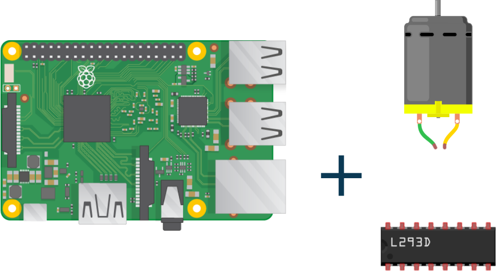
Step 1: Required Components
L293D H-Bridge Motor Driver x 1
DC Motor x 1
Raspberry Pi x 1
9V Battery x 1
Jumper Wires
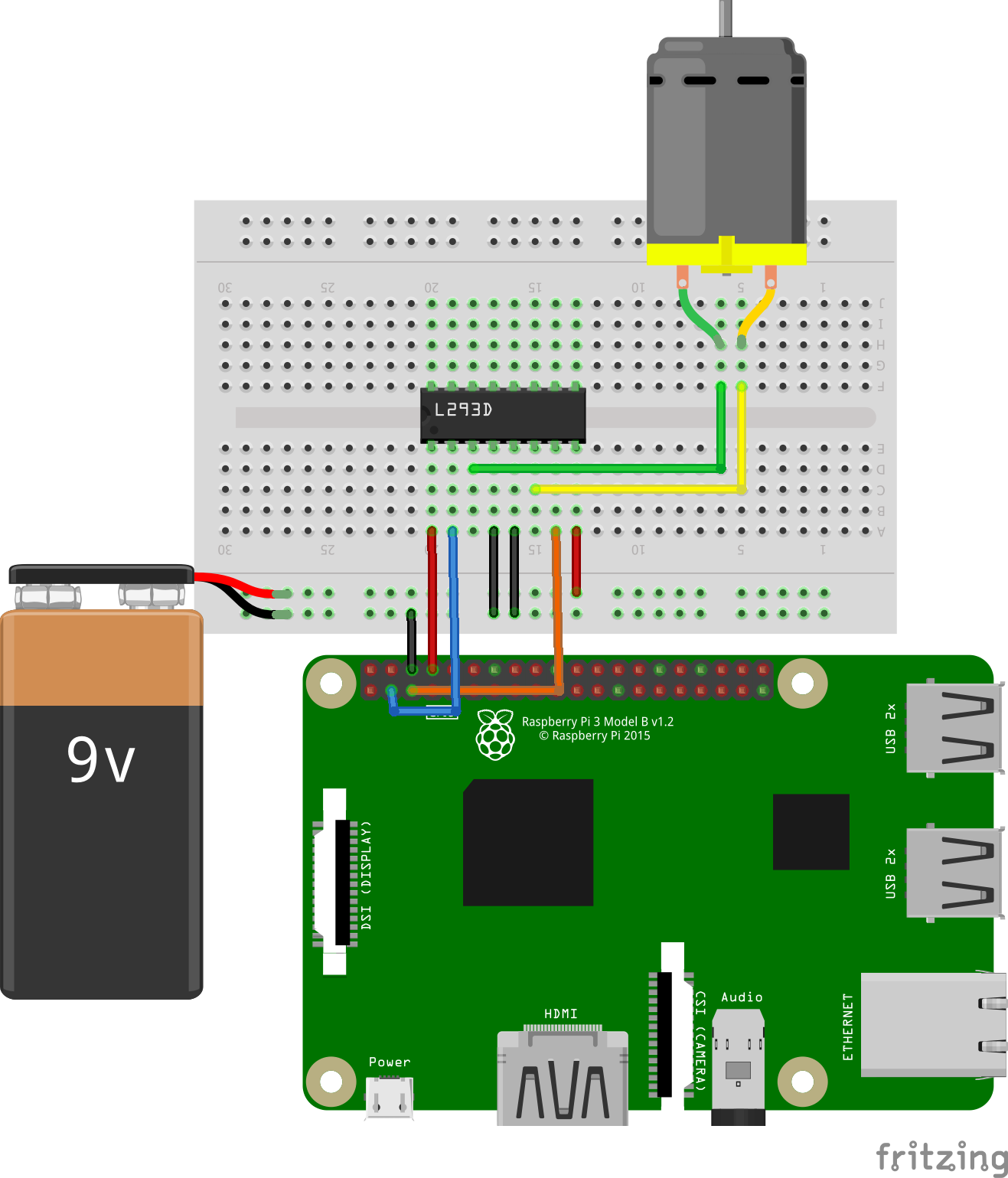
Step 2: Circuit Time
Make the circuit as per the given diagram. Connect motor input 1 to GPIO 3 and motor input 2 to GPIIO 5. Connect Enable pin to GPIO 8. The motor driver is provided an external 9V power supply using a 9V battery connected to the VSS pin. Connect GND pin to Raspberry Pi Ground.
Step 3: Code Time
This is code for H-Bridge Motor Driver in Raspberry Pi using python. First, import GPIO library and set pins to GPIO.BOARD mode. Then, declare GPIO 3 as input 1 and GPIO 5 as input 2. Also, declare GPIO 8 as to enable. Set these three pins in output mode. We are running motor only in the forward direction, so, set input 1 and enable to High, and input 2 to Low. If you want to run the motor in reverse direction set input 2 to High and input 1 to Low, keeping enable High.
Step 4: Run code to Raspberry Pi
Run the Python program in your Raspberry Pi after setting components as per the circuit diagram. The motor will start running in the forward direction.
For running python code in Raspberry Pi, visit: raspberrypi.org/documentation/usage/python/
Pin 16 (top left in the image) should be connected to 5V, it powers the darlington circuitry. It could work without, but not if you have a second motor attached.