Learn interfacing Light Dependent Resistor LDR in Raspberry Pi. We will learn how LDR works. LDR is a type of resistor whose resistance varies according to the surrounding light. Resistance will increase with the increase in light intensity. LDR also known as Photoresistor, are available in 5mm, 7mm, 10mm, and many other sizes. So, let’s start.
Step 1: Required Components
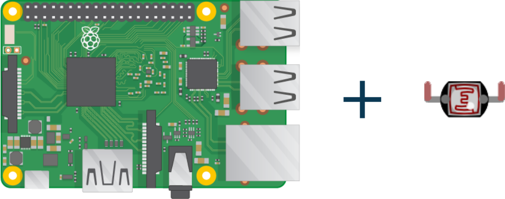
LDR (Light Dependent Resistor) x 1
Breadboard x 1
Raspberry Pi x 1
1µf Capacitor x 1
Jumper Wires
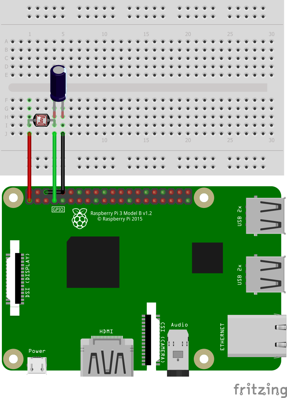
Step 2: Circuit Time
Make the circuit as per the given diagram. Connect one leg of LDR to VCC +5v. Now, connect the long leg of the capacitor and another leg of LDR on the same track of breadboard. The ground short leg of the capacitor.
Step 3: Code Time
This is code for interfacing LDR in Raspberry Pi. First of all, we have to import the LightSensor code for LDR from the gpiozero library. Assign GPIO pin to variable LDR and also pass the GPIO pin number as an argument to the LightSensor method. While loop print’s value of LDR.
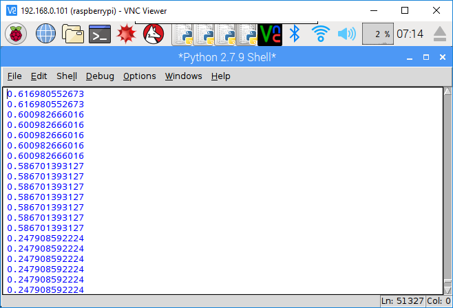
Step 4: Run code to Raspberry Pi
Run the Python program in your Raspberry Pi after setting components as per the circuit diagram. The LDR will give resistance to Raspberry Pi and Raspberry Pi. The screenshot of the output is given below.
For running python code in Raspberry Pi, visit: raspberrypi.org/documentation/usage/python/
It would be SUPER cool if you corrected the drawing, so the cap is correctly polarized. In the drawing, the cathode is connected to the ldr and the anode is connected to ground, and it should be the other way around, as the text explains.
Sorry for that. The issue is now changed.
Is it possible to connect several LDR’s to Raspberry and maintain Control of each in the Python script?
Yes it is possible by initializing multiple LDR in code and using it in loop.
This isnt work well, our metter blink so fast, and sensor didn’t catch it at all. Do you have any idea?
This is just what I have been looking for. One query though: in Step 2 you say “Connect one leg of LDR to VCC +5v”, but the illustration shows the LDR connected to pin 1, which is 3.3v, rather than one of the 5v pins 2 & 4. Which is correct? I think it probably should be 3.3v, but I don’t understand enough to be sure.