Learn how to Program ESP8266 ESP-12E with Arduino using FTDI USB to TTL Cable. You just need to install the ESP8266 board and make the circuit as per the below-given instructions. Learn the basics and features of ESP8266 ESP-12E.
Step 1: Required Components
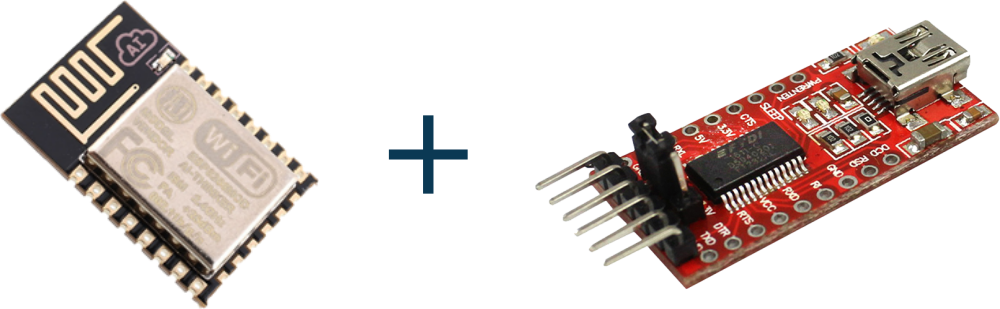
ESP-12E WiFi Module x 1
FTDI USB to TTL Serial Converter Cable x 1
Jumper Wires
Step 2: Circuit Time
Connect FTDI VCC to ESP8266 ESP-12E VCC and GPIO_2, RTS/CTS to CH_PD, DTR to GPIO_0, GND to GND and GPIO_15, TX to RX and RX to TX.
Step 3: Program ESP8266 ESP-12E
Make the circuit as per the above-given instructions. Connect the FTDI cable to the USB port. Select the proper board and programmer. Upload the code to ESP8266 ESP-12E.
Bootloader Modes of ESP-12E
Bootloader ModesThe bootloader can go into several modes depending on the state of GPIOs 0, 2 and 15. The two useful modes are the UART download mode (for flashing new firmware) and the flash startup mode (which boots from flash).
Flash Startup (Normal) GPIO0: 1 GPIO2: 1 GPIO15: 0
UART Download Mode (Programming) GPIO0: 0 GPIO2: 1 GPIO15: 0
SD-Card Boot GPIO0: 0 GPIO2: 0 GPIO15: 1
Learn basic information and uploading code using FTDI USB to TTL Cable.
Install ESP8266 boards to Arduino IDE.
Great delivery. Great arguments. Keep up the amazing effort.
Thank you. Please share it among your friends and network.
Why is reset pin not used? I thought the 8266 only went into programming mode at boot time? If it’s powered before you start to program wont this window have been missed?