Here, learn how to Program ESP8266 with Arduino using FTDI USB to TTL Cable. You just need to install the ESP8266 board and make the circuit as per the below-given instructions. Learn the basics and features of ESP8266. We are using the Blink LED program as a sample program.
Step 1: Required Components
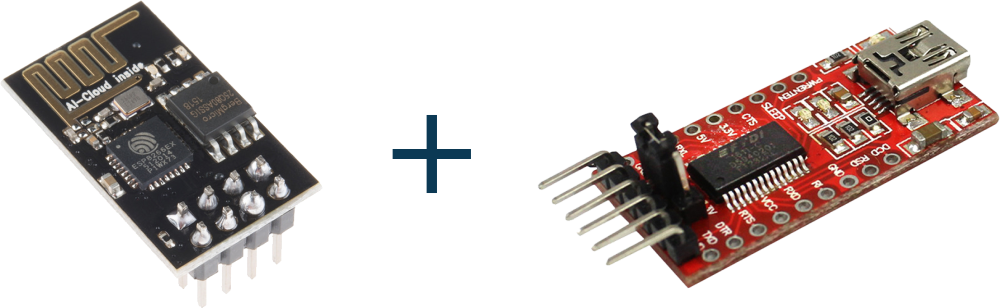
ESP8266 Module x 1
FTDI USB to TTL Serial Converter Cable x 1
Jumper Wires
The LED (for Blink LED Program)
Step 2: Installing Board to Arduino IDE
First, install ESP8266 to Arduino IDE. If you have already installed the board to boards manager of Arduino IDE, skip this step else follow the steps
- Start the Arduino IDE
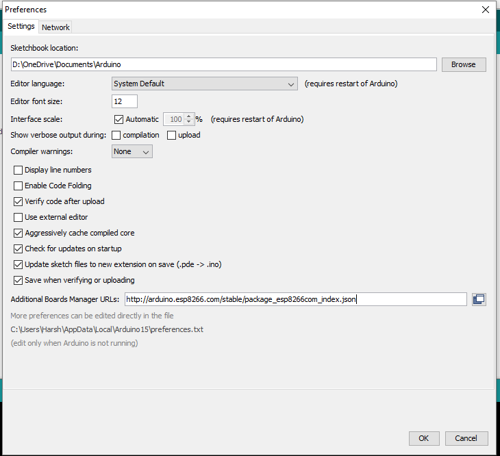
- Go to File > Preferences
- Add the below-given link to Additional Boards Manager URLs
- Go to Tools > Boards > Boards Manager…
- Search ESP8266
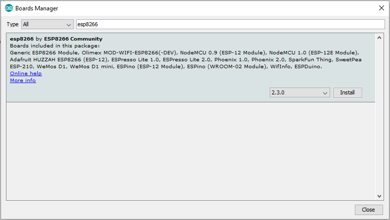
- Click the Install button to install the ESP8266 Board
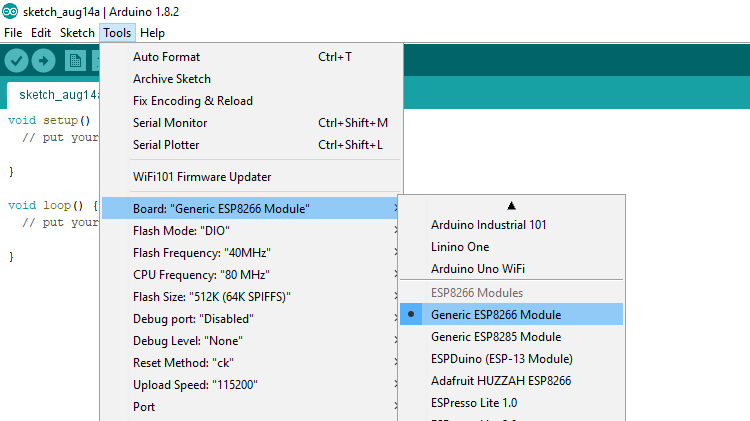
- Now close the Boards Manager window and select the Generic ESP8266 Module from the board selection list
- The installation of ESP8266 in Arduino IDE is done.
Step 3: Circuit Time
Connect FTDI VCC to ESP8266 ESP-01 VCC and CH_PD, GND to GPIO_0 and GND, TX to RX and RX to TX. GPIO_0 is Grounded to enable the programming mode of ESP8266.
Step 4: Program ESP8266 with Arduino using FTDI
Make the circuit as per the above-given instructions. Connect the FTDI cable to the USB port. Select the proper board and programmer. Upload the code to ESP8266 ESP-01. Sample program for Blink LED is as below
After the Arduino IDE shows done uploading of Blink LED program, connect the LED to GPIO_2 Pin of ESP8266. Please do not connect the LED before or at the time of uploading the program, it can cause some issues in uploading the program.
Learn basic information and uploading code using FTDI USB to TTL Cable.
any diagram could be usefull