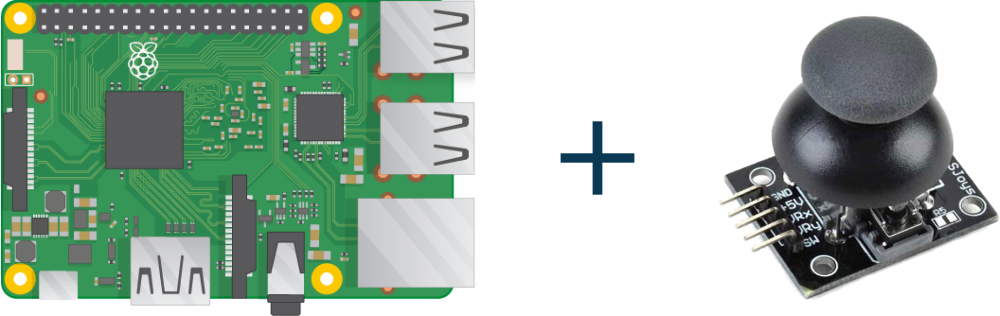
Learn the interfacing Analog Joystick Module in Raspberry Pi. Joystick module is the Analog module. Analog Joysticks is useful to add axis based controls. As the Joystick module provides analog outputs, we will use MCP3008 Analog to Digital converter. MCP3008 provides 8 analog channels with 10bit precision. So, let’s start.
Step 1: Required Components
Joystick Module x 1
Breadboard x 1
Raspberry Pi x 1
MCP3008 ADC converter x 1
Jumper Wires x 1
Step 2: Circuit Time
Make the circuit as per the given diagram. Connect VDD and VREF pins of MCP3008 to +3.3V of Raspberry Pi. Now, Connect AGND and DGND pins of MCP3008 to the ground of Raspberry Pi. Then, connect CS pin to GPIO 8, DIN to GPIO 10, DOUT to GPIO 9, and CLK to GPIO 11. Connect the VCC pin of Joystick to +5v of Raspberry Pi and GND pin of Joystick to GND of Raspberry Pi. Now, connect X to CH1 of MCP3008, Y to CH2 of MCP3008 and key to CH0 of MCP3008. The switch can be connected to GPIO pins of Raspberry Pi.
Step 3: Code Time
This is code for interfacing analog Joystick Module in Raspberry Pi. Readings from Joystick will be between 0 to 1023 as MCP3008 provides 10-bit precision. First, import necessary libraries. Then, open the SPI bus and write a function to read data from the SPI bus. Now, define channels of MCP3008 which are used. Loop takes readings of value provided by module and prints on the console.
Step 4: Run code to Raspberry Pi
Set the components as per the Circuit Diagram and run the above-given code in Raspberry Pi. Joystick Module will provide a reading of x and y-axis to Pi which will be displayed on the terminal.
For running python code in Raspberry Pi, visit: raspberrypi.org/documentation/usage/python/
Learn basic hardware information of Raspberry Pi 3.