Learn the interfacing Flame Sensor Module KY-026 in Raspberry Pi. The flame sensor will generate certain output on detection of flame. Measured input from the Sensor is then fed to the amplifier. Amplifier then sends analog data to the analog output pin of the module. In this, we are going to interface LED using the Flame Sensor Module KY-026 in Raspberry Pi. We are using ADS1115 16-Bit Analog to Digital Converter because Raspberry Pi doesn’t support analog input. So, let’s start.
Step 1: Required Components
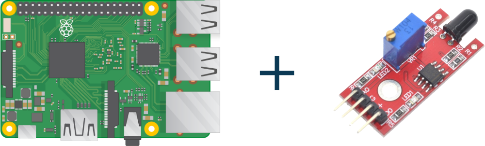
Flame Sensor Module KY-026 x 1
ADS1115 16-Bit Analog to Digital Converter x 1
Breadboard x 1
Raspberry Pi x 1
Jumper Wires
Step 2: Circuit Time
Make the circuit as per the given diagram. There is a total of four pins in KY-026 Flame Sensor VCC, GND, Analog output, Digital output. Connect Raspberry Pi 3.3v to VCC of Flame Sensor and VDD of ADS1115. Common all the three Ground Pins. Connect Flame Sensor Digital Output pin to GPIO24 of Raspberry Pi. A0 of ADS1115 to Analog Output of sensor. ADS1115 SDA to GPIO2 and SCL to GPIO3.

Step 3: Code Time
This is the code for interfacing Flame Sensor Module KY-026 in Raspberry Pi. Used time and Adafruit_ADS1x15 library in code. (If you don’t already installed Adafruit_ADS1x15 library then please install it first. Link for Library: Adafruit_Python_ADS1x15 Python library) .
Step 4: Run code to Raspberry Pi
Set the components as per the Circuit Diagram and run the above-given code in Raspberry Pi. It will print Flame Sensor output on the display.
For running python code in Raspberry Pi, visit: raspberrypi.org/documentation/usage/python/
Learn basic hardware information of Raspberry Pi 3.