Learn the interfacing Flame Sensor Module KY-026 in Arduino. The flame sensor will generate certain output on detection of flame. Measured input from the Sensor is then fed to the amplifier. Amplifier then sends analog data to the analog output pin of the module. In this, we are going to interface LED using the Flame Sensor Module KY-026. So, let’s start.
Step 1: Required Components
Flame Sensor Module KY-026 x 1
Breadboard x 1
Arduino Uno Board x 1
Jumper Wires
Step 2: Circuit Time
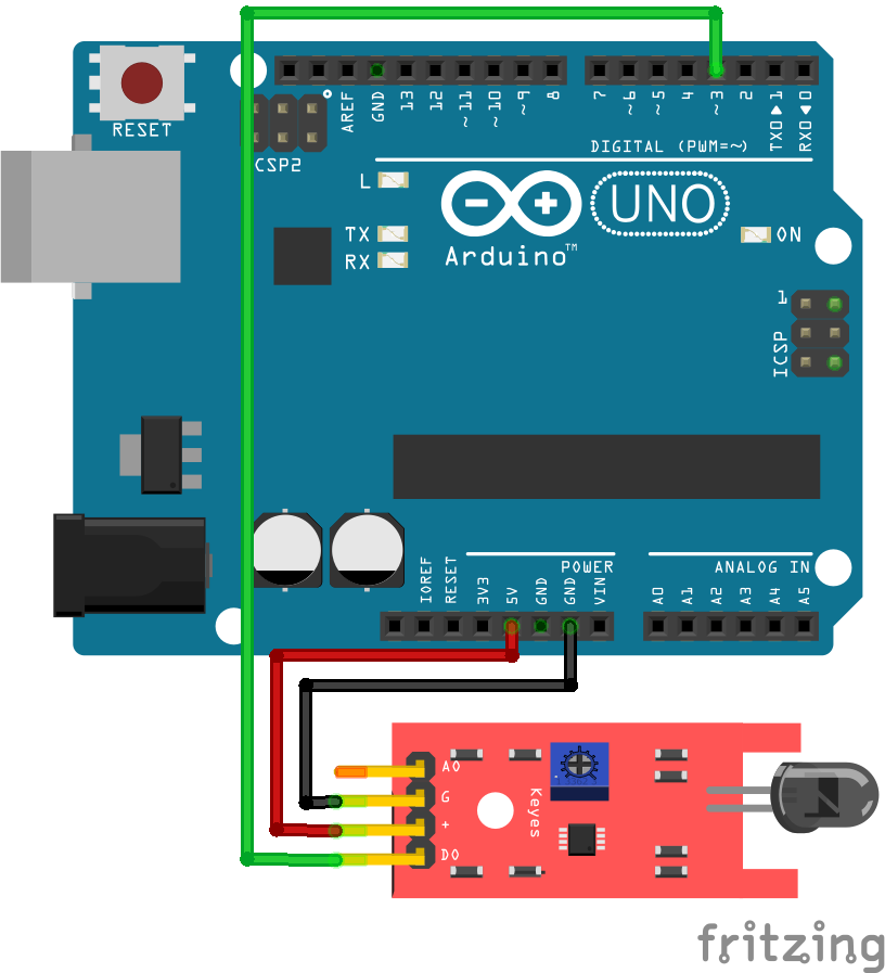
There are four pins in Flame Sensor Module, VCC, GND, Analog output, Digital output. Connect VCC of the module to +5v of Arduino and GND of the module to Arduino Ground. Then, connect the Digital output of the module to pin 3 of Arduino.
Step 3: Code Time
This is code for interfacing of the Flame Sensor Module with Arduino. Firstly, declare pins for LED, digital output. In Setup, set LED pin in output mode and sensor pin in input mode. This will make pin 3 of Arduino receive inputs from the sensor and provide certain output to an LED. In the loop, check the status of the sensor pin. If the status of the sensor pin is HIGH then provide a HIGH output to LED or else provide a LOW output to an LED.
Step 4: Upload the code to Arduino
Upload the above-given code to the Arduino Uno Board after the components are set as per the Circuit Diagram. On detection of flame, you will notice LED connected to pin 3 is turned on.
Learn more information about uploading code to Arduino Uno.