Control the LED connected to the ESP8266 webserver. Initially create a simple web server and connect an LED to ESP8266. Now, the user can open the webserver and control the LED by toggling the buttons. In this, we have only used LED, but you can also connect various different sensors. However, there are only two GPIO pins on ESP8266-01 so only one sensor can be connected to ESP8266 at a time. Anyways, Let’s start.
Step 1: Required Components
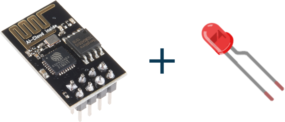
ESP8266 WiFi Module x 1
LED x 1
Resistor (220Ω) x 1
Jumper Wire x 1
BreadBoard (optional) x 1
3.3V Linear Voltage Regulator (LD1117) x 1
Arduino Uno Board (Only for uploading program to ESP8266) x 1
Step 2: Circuit Time
- Connect CH_PD and Vcc to +3.3v pin of LD1117.
- Connect GND pin to digital ground. (you can use a common ground for both ESP8266 and LD1117).
- Connect the Anode of LED to GPIO0 0 with resistor in-between GPIO and Anode.
- Connect Cathode to Ground.
- Provide power supply to LD1117.
Step 3: Code Time
In the code, the server interprets requests by the browser. Buttons used in the webpage are used to set the status of LED to on or off.
Step 4: Upload code to ESP8266
Simply upload the code using the procedure mentioned below-given link. After successfully uploading the code, remove TX and RX pins.
Learn more about uploading code to ESP8266.