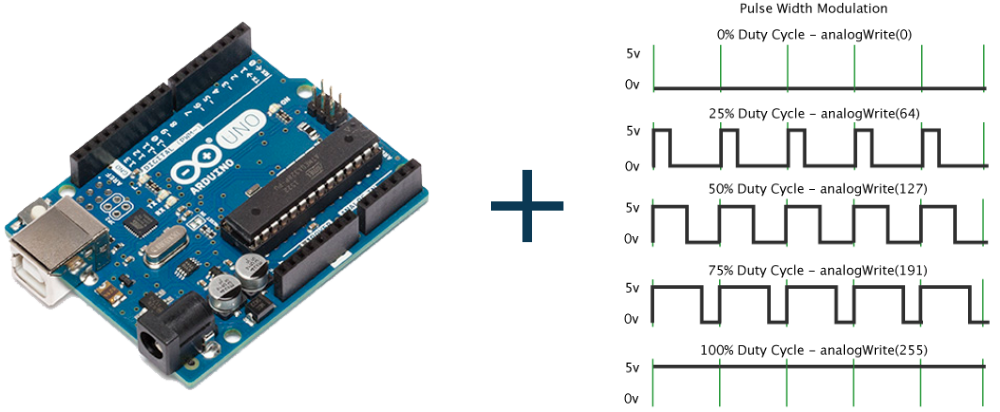
Pulse Width Modulation, or PWM, is a technique for getting analog results with digital means. It creates the square waves which switch between on and off. This on-off pattern can simulate voltages in between full-on and off by changing the portion of the time the signal spends on versus the time that the signal spends off. The duration of “on time” is called the pulse width. To get varying analog values, you change or modulate, that pulse width. Let’s learn using PWM in Arduino and graphical representation of PWM.
Graphical Representation of PWM in Arduino
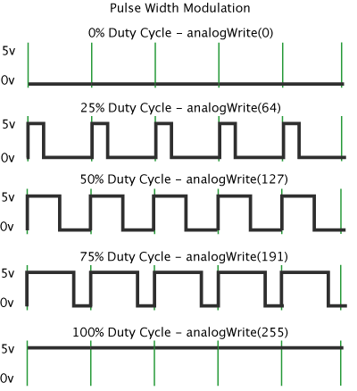
In the graphic below, the green lines represent a regular time period. This duration or period is the inverse of the PWM frequency. In other words, with Arduino’s PWM frequency at about 500Hz, the green lines would measure 2 milliseconds each. A call to analogWrite() is on a scale of 0 – 255, such that analogWrite(255) requests a 100% duty cycle (always on), and analogWrite(127) is a 50% duty cycle (on half the time) for example.
Once you get this example running, grab your Arduino and shake it back and forth. What you are doing here is essentially mapping time across space. To our eyes, the movement blurs each LED blink into a line. As the LED fades in and out, those little lines will grow and shrink in length. Now you are seeing the pulse width.
General uses of PWM Pins.
- Dimming an LED.
- Generating audio signals.
- Providing variable speed control for motors.
- Generating a modulated signal, for example, to drive an infrared LED for remote control.
Using analogWrite in Arduino
There are total six pins PWM pins in Arduino (Pin 3, 5, 6, 9, 10 and 11)
analogWrite is used to give Analog output from above-given pins.
Syntex: analogWrite(pin, value) where pin= the pin to write to. Allowed data types: int and value= the duty cycle: between 0 and 255.

